Installation of these kits is not legal unless installed with an Engineering Order from the GFA. The order is raised for each individual registration and can not be applied to any other aircraft other than that in the E/O. The E/O will also advise the qualification level required of the installer.
Final debburring and cleaning of the Interface Block and Filter Block is the responsibility of the installer. I have deburred the external sect’s of theses units but the internal sect’s where the holes intersect is a time consuming job so have left it for others as I can not charge for my time.
Final inspection and cleaning of the Hydraulic Fittings and hoses is also the responsibility of the installer.
Hoses have been tested to 1500 psi.
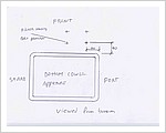
I just realised I forgot to stamp In and Out on the blocks so please refer to the attached drawing. The interface block is staright forward. The Filter Block just remember that the Port that intersects with the 3/4″ UNF tapped hole for the threaded sleeve that connects to the filter is OUT. It you get it the wrong way the paper element will swell out and seal to the canister wall blocking of completetly.
I am not a fan of PTF tape in this sort of application so I used a Hydraulic sealant from Loctite on the installation of the nipples and elbows in to the alloy blocks.
If you do use this it tends to be for keeps in alloy so dry assemble the entire system first and work out the best angles of the elbows in relation to the blocks first then assemble with sealant.
Respect the wall thickness of the alloy section when tensioning.
The threaded sleeve for cartridge connection must be installed with the short thread end in to the housing. I used thread sealant again to lock it rather than peening. This sealant is rated to higher temps than we are interested in.
1/8″ BSPT unbrako plug fits in to Interface block to block of cross drilling. This drilling can also be used as an installation point for a second Pressure Sensor if you wish to check pressure drop over filter. Worth note if you want to do this do it rather than plugging as I said the sealant tends to be for keeps.
The normal Toyota filter cartridge is small so Rob and I have been using the bigger alternative as it is of larger capacity and hopefully reduces pressure drop.
Toyota part number 15601-03010
Obey the instructions on the filter of course and do not over tighten.
A hose clamp fitted around the Cartridge with the screw assembly hard against the panel in the unscrew direction makes a good secondary lock.
With the larger unit there is not a great deal of clearance between it and the panel the housing it screwed to so if it is a problem fit washers between the housing and the panel to lift it a bit.
Drill heads and wire lock bolts holding housing to panel.
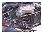
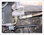
Attached file of installation.
Missing from the photo is the entry of hose through baffle on Starb side. This is made at the rear in both sides in the horizontal face. This provides for wide sweeping bends which all but eliminates the problem of fatigue in the wire braid. Best part of this style of hose is that problems are detectable long before failure. Just like checking control cables if you run your hand down it and get pricked then broken strands are present.
The lining is Teflon and has a temperature operating range of over 4 times that of the engine.
Tefflon also does not go hard unlike Nitrile with age so life expectancy for the hose is more years than I have left flying in me.
In the kit is also rubber grommets. These go in the baffle to stop hose rubbing on alloy sheet. We ground a shallow champher on the end of a bit of steel tube to create a sharp edge and used it as a hole punch. Best used on the grommet centre against a bit of wood and pressed through by sandwiching in a vise.
I think thats about it.
Cheers
Nige


